If you are thinking of soldering a piezo disc directly to a guitar cable, stop and get some help. This is the help. It is a high fidelity, Externally powered piezo disc preamp with adjustable gain and optional input attenuation on a circuit board. Put it between the disc and cable and you will get much better sound.
This is an updated version of the popular
Marshmallow DIY Kit preamp, with an added -24 dB attenuation feature. It has super-low noise even at high gain. It has a proper high-impedance input buffer so that it has good bass response and you won't get that awful sound associated with piezo discs soldered directly to guitar cables. It has optional input attenuation so you can record very loud sounds without clipping.
This board has line-level output and is externally powered, meaning it needs to be powered with a battery, DC power supply, or similar. There exists a
Phantom Powered version of this board here, which has mic-level output and can be powered by a microphone input on a recording interface.
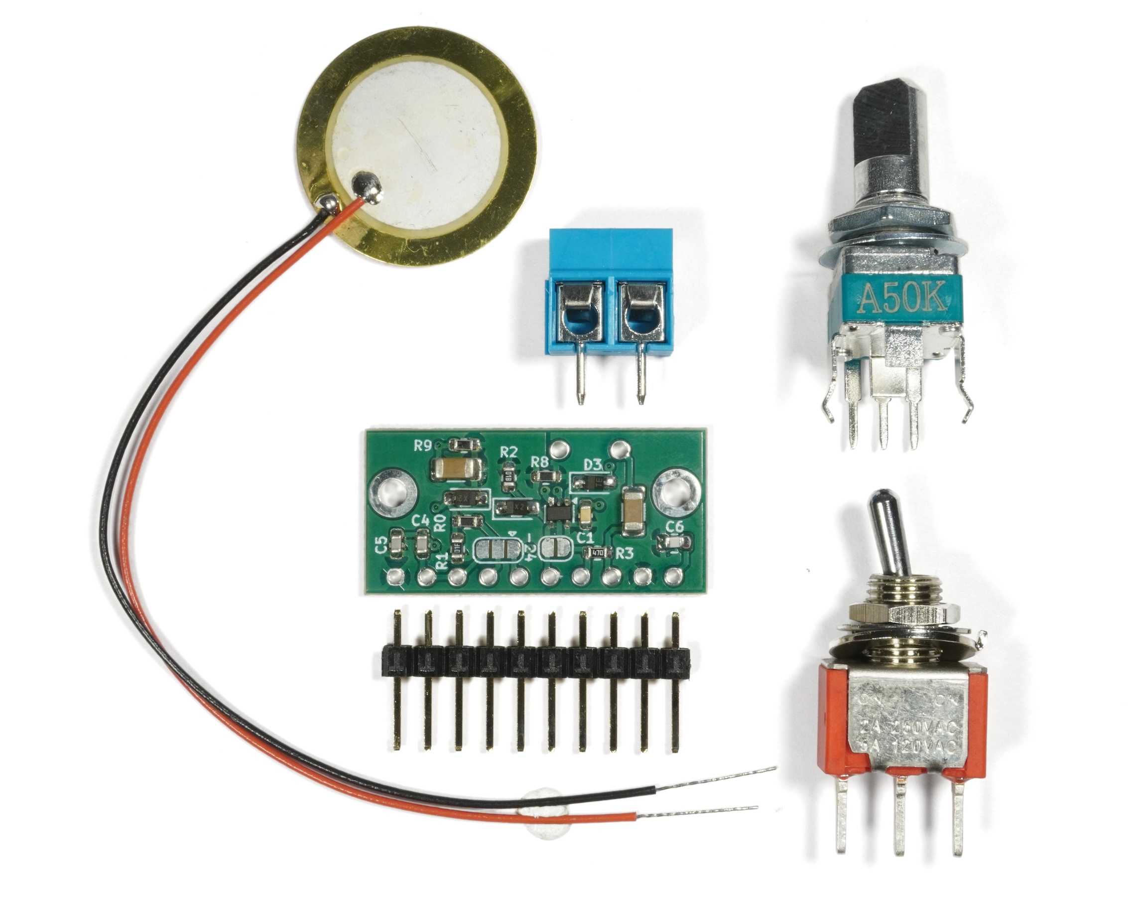
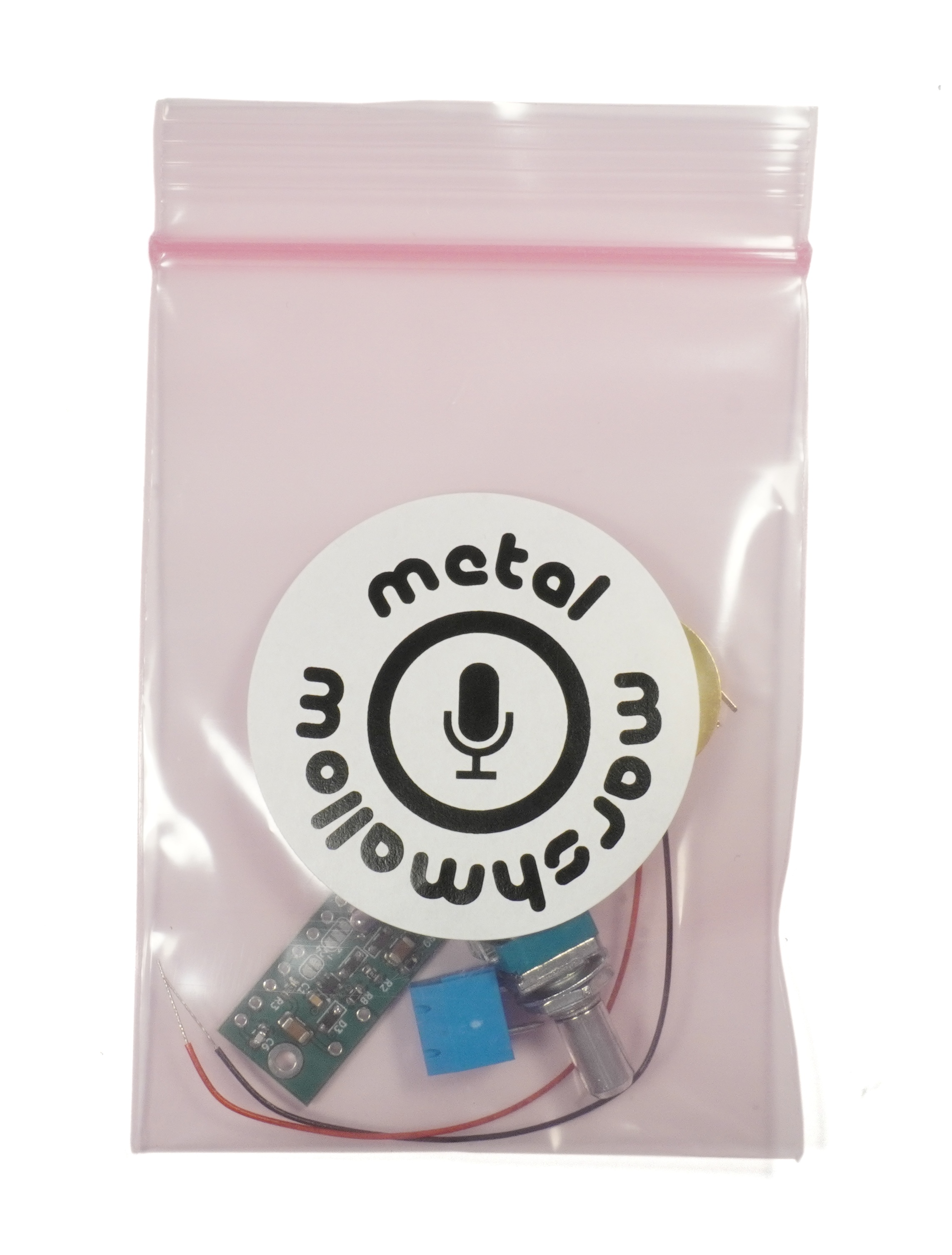
Included
- Marshmallow DIY V2 Piezo Preamp
- 20mm Piezo Disc
- 10-Pin Header
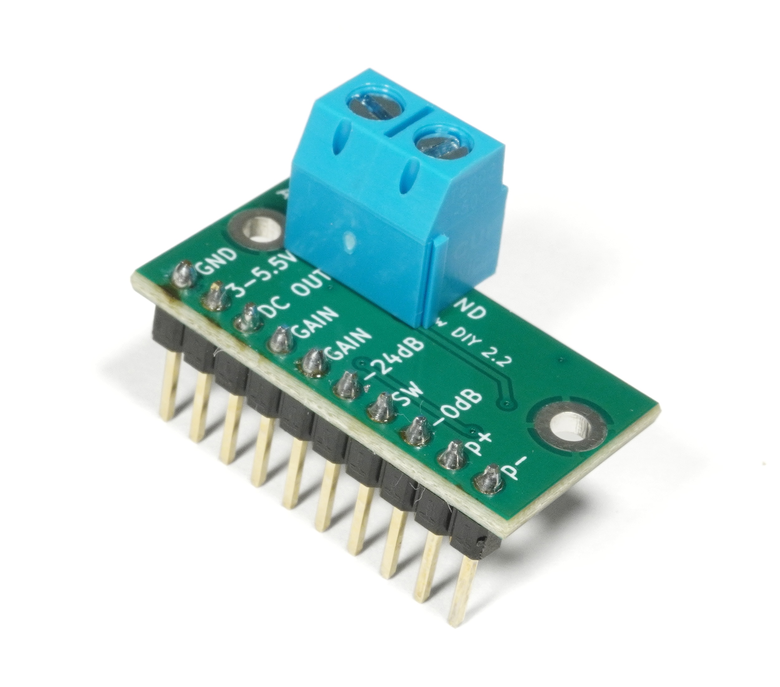
- 2-Position Terminal Block
- 50kΩ Log Potentiometer with 6mm D-shaft
- 2-Position Switch
Not Included
To facilitate maximum flexibility, this kit does not come with audio cable, connectors, or a battery or power supply, since what you need for this will depend on what you are building. Standoffs are not included as they were in previous versions of the kit.
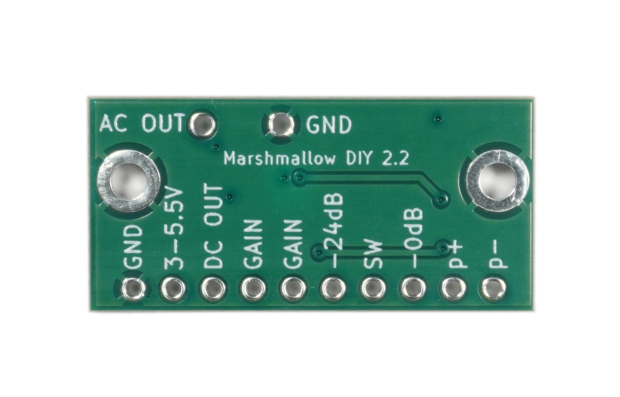
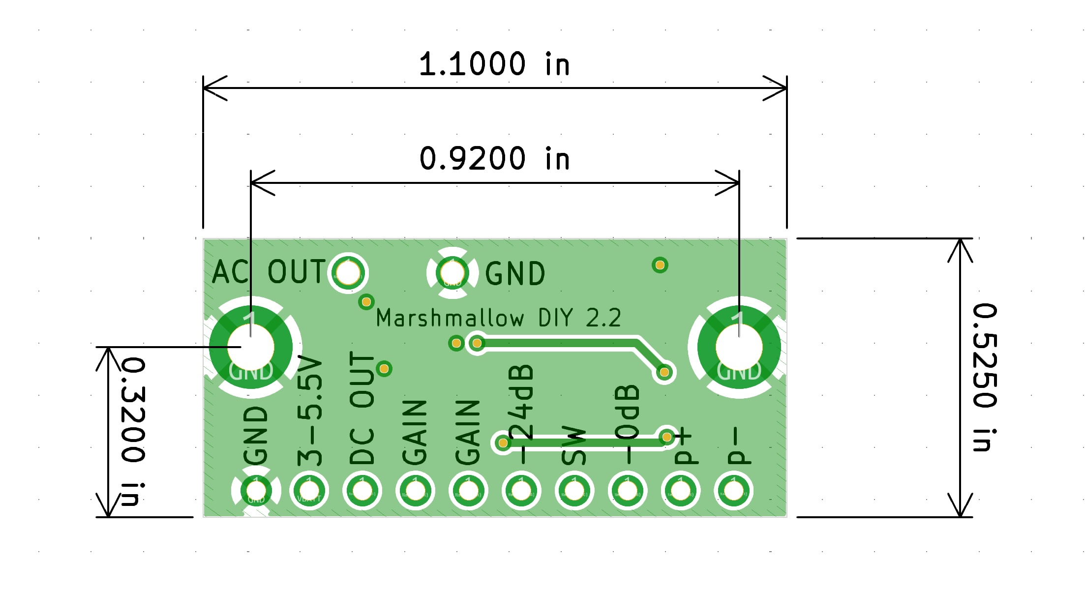
Pin Description
- p+ Connection for the positive lead of a piezo disc. By convention the inner crystalline part of the disc is considered as positive.
- p- Connection for the negative lead of a piezo disc. By convention the outer brass part of the disc is considered as negative.
- 0dB Connecting this to the SW pin will disable input attenuation, so the input will not be attenuated. Do this if you plan on recording quiet sounds.
- SW Switch pin. This pin must be connected to either the 0dB or -24dB pins in order to select the input attenuation level desired. If this pin is left unconnected, the preamplifier will not work and the output will be silent. A switch is included in the kit for this purpose. Alternatively, the attenuation level can be permanently fixed by placing a solder bridge on the relevant solder pad on the board. This is discussed further in the application notes below.
- -24dB Connecting this to the SW pin will enable -24dB of input attenuation, so the input will be attenuated by this amount. Do this if you plan on recording loud sounds.
- GAIN Connect a resistor, or the provided potentiometer, between the two GAIN pins to set the gain. Without a resistor, the gain will be unreasonably high and the audio will be very distorted. Alternatively a chip resistor or solder bridge can be placed between the solder pads on the board to permanently fix the gain. This is discussed further in the application notes below.
- DC OUT DC-coupled audio output. Use this to connect the preamp to other chips on a circuit board. For example, if you are designing a PCB that has this preamp going into a codec chip, you might use the DC output for this. If, on the other hand, you plan on plugging this preamp into a regular mixer or audio recording interface, you can leave this pin unconnected and use AC OUT instead.
- 3-5.5V This is the positive side of the power input to the board. Connect the positive terminal of a lithium battery, DC power supply or other power source here. This board does not have a regulator, o if you want to use more than 5V you will need to regulate it down first.
- GND This is the negative side of the power input to the board. Connect the negative terminal of a battery or DC power supply here.
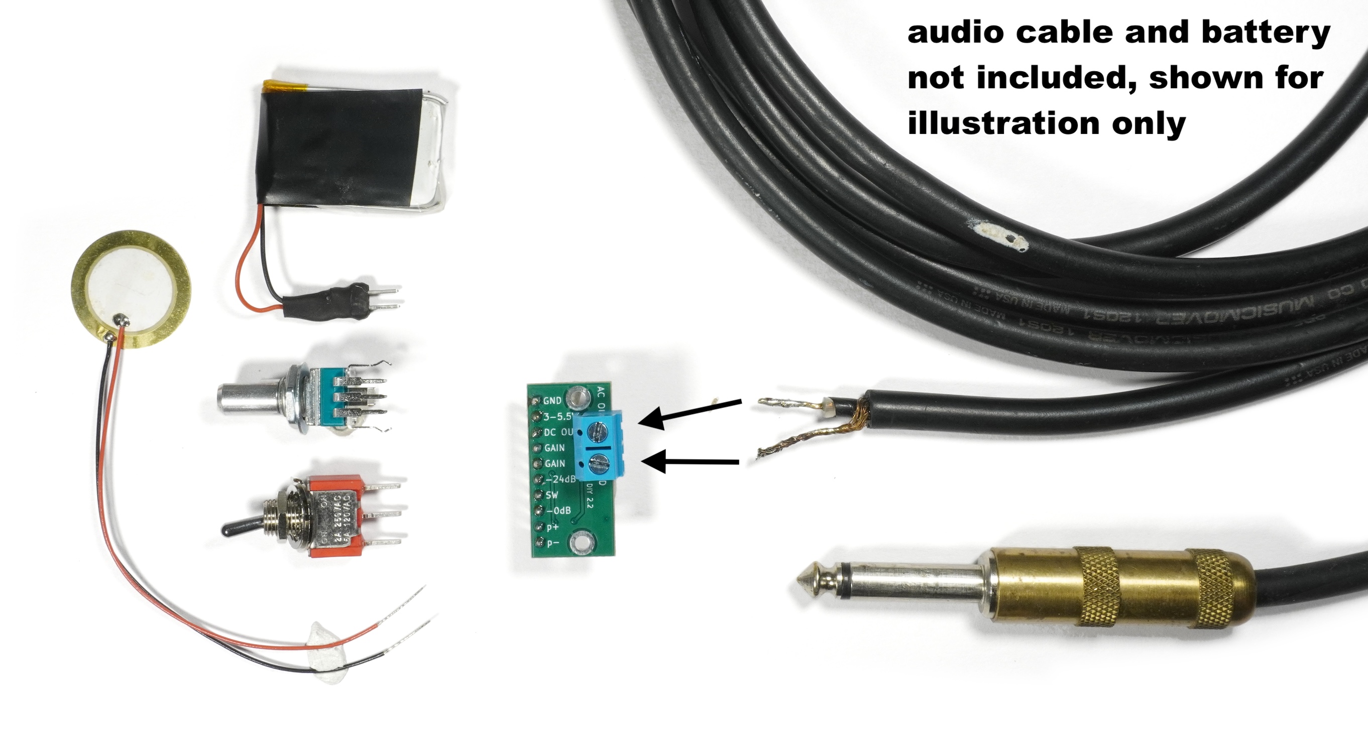
- AC OUT AC-Coupled audio output. Connect the inner conductor of an instrument cable here. On the far end of the cable, the inner conductor should connect to the the tip of a TS audio plug, which you can plug into a line-input on a mixer, audio recording interface, or other audio hardware that accepts line-level input. The cable can either be soldered directly to the board, or the included terminal block can be soldered to the board, and the cable connected to that.
- GND The second ground pin is where you can connect the outer shield part of the instrument cable that connects this preamp to your audio recording interface. On the far side of the cable, the shield should be connected to the sleeve of the TS audio plug which is to be plugged in to your recording equipment.
- Mounting Holes To reduce hum, the board and piezo disc should be enclosed completely in metal, which should be grounded. The metal could be a metal box or aluminum foil. If using foil, isolate the disc by covering it in a layer of tape before covering it in foil, the disc itself should not contact ground. The 2 large holes on the sides of the board are ground and are meant to facilitate connecting the board ground to a metal box. The mounting holes are designed for M2.5 standoffs (not included).
Application Notes
Piezo
- The preamp is optimized to work with either the piezo disc included in the kit, or with Metal Marshmallow Morsel. It can be used with other piezo discs or piezo films although the exact frequency response will vary slightly.
- The high-impedance input required by piezo discs makes this preamp sensitive to EMI (hum). For optimum EMI rejection, it is recommended that the piezo disc should have short leads and should be as close to the board as possible. Everything should be enclosed in grounded metal. If the microphone needs to be far from the audio recording interface, it is better to have a short distance between the piezo disc and the preamp, and a longer cable between the preamp and the recording interface. If a longer cable is from piezo to preamp is needed, it is recommended to use a high-quality microphone cable with two inner conductors and a high-coverage braided shielded. If a non-DIY solution is desired, Metal Marshmallow Morsel is specifically designed and tested for this application. Its 3.5mm plug should be connected to the preamp as follows:
- Tip → p+
- Ring → p-
- Sleeve → GND
A 3.5 mm receptacle is not included in this kit.
Attenuation
- If fixed input attenuation is desired, a solder bridge may be placed across the pads adjacent to the SW pin. Bridging the center and right pads results in -24dB attenuation. Bridging the center and left pads results in 0dB attenuation. If the pads are bridged, no further connection is required to the SW pin.
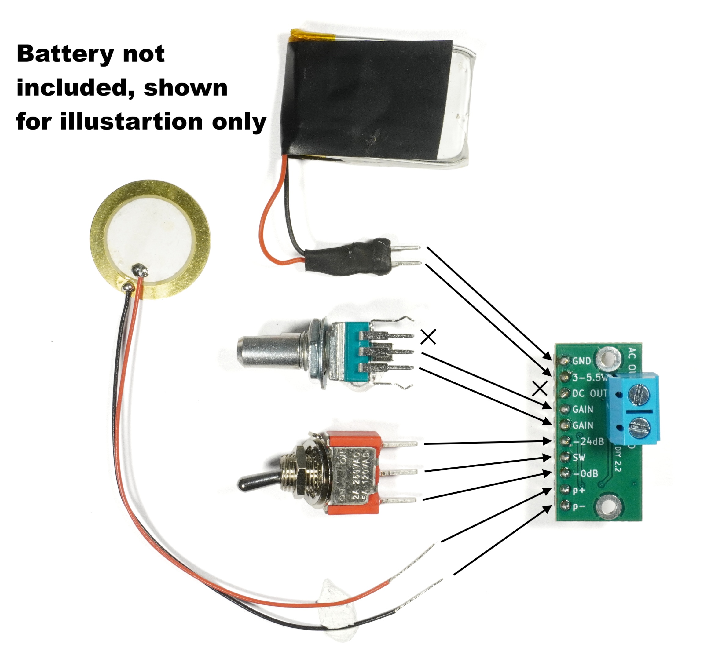
- If selectable attenuation is desired, the provided switch may be connected to the SW pins as shown in the diagram included in the product images. Note that switching the switch left connects the right two pins, and vice verca.
Gain
- If a fixed gain is desired, a chip resistor may be soldered across the solder pads adjacent to the GAIN pins. If a fixed gain of 1 is desired, these pads may be bridged with solder. No additional resistor will then be needed between the GAIN pins.
- If an adjustable gain is desired, it is recommended to use a potentiometer with a logarithmic taper, as is included in the kit.
- The gain is given by G = 1 + R/1000
- Alternatively R = (G - 1) * 1000, where G is the voltage gain and R the resistance in Ohms.
- Useful gains range from roughly 1x to 50x (0dB to 34dB), corresponding to 0 to 50k Ohms. See the table below for more details
| R |
G |
G dB |
| 0 |
1 x |
0 dB |
| 1k |
2 x |
6 dB |
| 2.2k |
3.2 x |
10 dB |
| 4.7k |
5.7 x |
15 dB |
| 10k |
11 x |
21 dB |
| 15k |
16 x |
24 dB |
| 33k |
34 x |
31 dB |
| 50k |
51 x |
34 dB |
Tech Specs
| Size |
1.1 x 5.25 |
in |
| Current Consumption |
1.5 |
mA |
| Bandwidth |
1.5 to 530,000 |
Hz |
| Output Level |
Line Level |
- |